Tunnel – Monitoring of 7 meters with pulse outputs via MQTT with alarm to detect the opening of the meter access door.
¿Buscas alguna otra cosa?
Scenario details:
- 7 counters with pulse output need to be monitored. Therefore, a modem with 7 pulse counter inputs is required. The accumulated pulses must be sent to a web platform via MQTT every 60 minutes
- The meters will be installed in manholes and register boxes which are locked. It is necessary to monitor the status of the door and, if it is opened, a message with the status of the door must be sent to the Web platform via MQTT. In this way, from the control post they will have proof that said location should be reviewed
Solution: MTX-Tunnel firmware + MTX-IoT-S 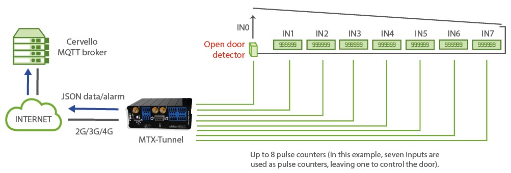 Configuration file config.txt (master):
| Configuration | Observations |
| GPRS_apn: movistar.es GPRS_login: MOVISTAR GPRS_password: MOVISTAR GPRS_timeout: 0 MTX_PIN: 0000 MTX_mode: none MTX_model: 199801422 MTX_ping: 30 MTX_pingIP: 8.8.8.8 MTX_numGSMErrors: 180 MTX_TPServer: es.pool.ntp.org MTX_TPServer2: 2.europe.pool.ntp.org MTX_TPProtocol: ntp SMS_allPhones: on SMS_sendIP: on SMS_ATEnabled: on SMS_ATResponse: on MQTT_enabled: on MQTT_server: tcp://broker.release.cervello.io.com:1883 MQTT_id: psdjs334jjsd8345 MQTT_login: 3ddg435g67899 MQTT_password: 2345433456567 MQTT_attopic1: /cervello/devices/[MQTT_ID]/rpc MQTT_atrtopic: /cervello/devices/[MQTT_ID]/rpc/response MQTT_qos: 1 MQTT_keepalive: 60 MQTT_defaultIOQos: 0 MQTT_defaultIOTopic: IOCHANGE GPIO_mode0: input GPIO_config0: mqtt;2;0 GPIO_mode1: input GPIO_config1: counter GPIO_mode2: input GPIO_config2: counter GPIO_mode3: input GPIO_config3: counter GPIO_mode4: input GPIO_config4: counter GPIO_mode5: input GPIO_config5: counter GPIO_mode6: input GPIO_config6: counter GPIO_mode7: input GPIO_config7: counter LOGGER_enabled: on LOGGER_registerSize: 600 LOGGER_numRegistersFlash: 1500 LOGGER_mode: mqtt LOGGER_mqttTopic: /LOGGER LOGGER_ioPeriod: 3600 DNS_enabled: on DNS_mode: mqtt DNS_mqttTopic: /dns DNS_period: 600 | APN GPRS provided by the GSM operator GPRS Login GPRS Password Modem is always GPRS connected Pin of the SIM GPRS connection server type Modem model Ping time to oversee connection Google IP (f.e.) to ping Reset if no registration in the GSM network in 1800 seconds NTP1 time server NTP2 time server NTP protocol Send SMS with commands from any phone Modem responds to a missed call/SMS Commands can be sent to the MTX by SMS MTX responds with an SMS to a command SMS MQTT service enabled Broker IP/DNS specified, including identifying port Identifier Username Password MQTT topic to send AT commands Topic to send replies to commands to QoS established Connection keep alive (60 seconds) Qos for the topic defaultIOTopic Topic MQTT to send fast telemetries GPIO0 configured as input GPIO0 MQTT configuration. Gate status GPIO1 configured as input GPIO1 MQTT configuration as pulse counter GPIO2 configured as input GPIO2 MQTT configuration as pulse counter GPIO3 configured as input GPIO3 MQTT configuration as pulse counter GPIO4 configured as input GPIO4 MQTT configuration as pulse counter GPIO5 configured as input GPIO5 MQTT configuration as pulse counter GPIO6 configured as input GPIO6 MQTT configuration as pulse counter GPIO7 configured as input GPIO7 MQTT configuration as pulse counter Logger on to store readings Internal registry size Max. number of registries Sending mode via MQTT Sending to MQTT broker topic Period of data sendig Status data sending activated MQTT sending mode Topic where status data are sent One sending every 600 secs (5 mins.) |
Details:
- The configuration of the inputs as “mqtt; 2; 0; 1; / DINPUT” indicates the following. Remember that all parameters are separated by semicolons ;
“mqtt” > The input is configured to send the states of the digital inputs by MQTT
“2” > The 2 indicates that the digital input is configured to send an MQTT message both for activation of the input (when it closes taking it to ground) and for deactivation of the input (when it opens). In case you want to send an MQTT message only when closing the entry (bringing it to ground), you should indicate a value of “1”
“0” > Indicates the timeout of the digital input. This means that the change of the digital input will be sent whenever it occurs. If, for example, a value of “10” was configured, as occurs with GPIO4 and GPIO5, even if multiple activations occur in the digital input, more than 1 MQTT message will never be sent in those 10 seconds
“1” > The QoS of the MQTT message indicates the message, which can have the value 0.1.2
“/DINPUT” > Indicates the topic to send the MQTT message to - The configuration of the inputs as “counter” indicates the following:
“counter” > The input is configured as a pulse counter - The sending format of the GPIO0 input messages (the input that controls the opening of the door) follows the JSON structure, shown in the following example:
{
“IMEI”:”354033091487838”,
“TYPE”:”DINPUT”,
“DATA”:
{
“GPIO”:0,
“VALUE”:1
}
}Where:
– IMEI: indicates the IMEI of the MTX modem
– TYPE: indicates the type of frame. DINPUT = Digital Input
– DATA: contains a JSON with the event data
– GPIO: indicates the GPIO index (0… 7)
– VALUE: indicates the value of the input (0,1) - The sending format of the IOS messages, where the data of the counters are included, is as follows:
{
“IMEI”:”354033091487838”,
“TYPE”:”IOS”,
“TS”:”19/01/20 07:16:08”,
“IO0”:0,
“IO1”:0,
“IO2”:0,
“IO3”:0,
“IO4”:0,
“IO5”:0,
“IO6”:0,
“IO7”:0,
“AD0”:0,
“AD1”:0,
“CO0”:”10005”,
“CO1”:”11005”,
“CO2”:”14303”,
“CO3”:”16001”,
“CO4”:”14425”,
“CO5”:”11901”,
“CO6”:”11124”,
“CO7”:”15373”
}Where:
– IMEI: indicates the IMEI of the MTX modem
– TYPE: indicates the type of frame. IOS
– TS: timeStamp
– IOx: 0.1 (state of the digital input, where x = 0, … 7)
– COx: counters accounts, where x = 0 … 7)