Tunnel – Periodic monitoring by 4G/3G/2G of 0-10V sensor activating the power supply of the sensor through a relay output of the modem. Sending to web server using HTTP GET.
¿Buscas alguna otra cosa?
Scenario details:
- It is intended to monitor a 0-10V sensor with a 4G/3G/2G modem
- The modem and the sensor will be powered by solar panels, so energy consumption is important
- For this reason, the sensor to be read will be powered through the internal relay with the MTX-IOT-S modem associated with its GPIO8 output. That is, the MTX-IOT-S modem, before reading the sensor, will activate the GPIO8 (internal relay) to supply said sensor 0-10V. After a 5 second wait for sensor stabilization, the MTX-IOT-S modem will read the sensor that will be connected to its AD0 input (which allows an input between 0 and 50V) and then deactivate the relay again to save consumption
- The monitoring must be at certain times (at 00:00 UTC, 06:00 UTC, 14:30 UTC and 18:30 UTC) the data will be stored in the flash memory of the modem (datalogger) and will be sent to a server web via HTTP GET as soon as there is 4G/3G/2G coverage
Solution: MTX-Tunnel firmware + MTX-IoT [4-S-N-N]-STD-N 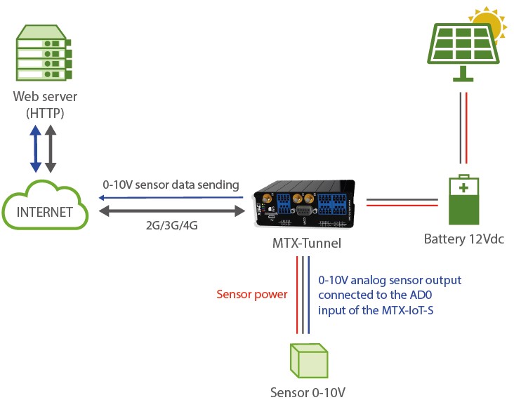
Configuration example (config.txt file) for the indicated scenario:
| Configuration | Observations |
| GPRS_apn: movistar.es GPRS_login: MOVISTAR GPRS_password: MOVISTAR GPRS_timeout: 0 MTX_pin: 0000 MTX_model: 199802407 MTX_TPProtocol: ntp MTX_TPServer: ntp.roa.es MTX_TPServer2: es.pool.ntp.org MTX_TPFormat: unix MTX_mode: none MTX_ping: 30 MTX_pingIP: 8.8.8.8 FIREWALL_enabled: off SMS_allPhones: on SMS_sendIP: on SMS_ATEnabled: on SMS_ATResponse: on GPIO_mode8: output GPIO_config8: normal ADC_mode0: voltage GPRS_apn: movistar.es LOGGER_enabled: on LOGGER_server: www.metering.es/json/set.asp?data= LOGGER_password: 12345678 LOGGER_numRegistersFlash: 1500 LOGGER_registerSize: 300 LOGGER_numRegistersRam: 0 LOGGER_httpMode: getjson TELNET_enabled: on TELNET_login: user TELNET_password: 1234 TELNET_port: 20023 |
GPRS APN provided by GSM operator GPRS Login GPRS Password Modem is permanently connected to GPRS PIN if it has one Device model Time synch. protocol Time server (the MTX must sync the time) Backup time server Sent JSON format Gateways used Every 30 minutes PING check Google IP (f.e.) to ping Authorized IPs IP by SMS authorized IP by SMS authorized AT by SMS allowed SMS AT responses activated GPIO configured as output Configuration of GPIO ADC configured as voltage GPRS APN provided by GSM operator Logger on to store readings Data sending URL “P” field of JSON Registry numbers in flash Registry size in flash Number of readings stored in RAM Data sending mode to server Telnet status Telnet login Telnet password TCP port for telnet |
Details:
- The frame sent to the server has the following JSON format
31/01/2020 12:20:33 — {“IMEI”:354033091487838,”TYPE”:”IOS”,”TS”:”2020-01-05T06:00:33Z”,”P”:”12345678”,”IO0”:1,”IO1”:1,”IO2”:1,”IO3”:1,”IO4”:1,”IO5”:0,“IO6”:0,”IO7”:0,”IO8”:1,”AD0”:5935,”AD1”:0}
Where:
TYPE: IOS frame type
IMEI: internal identification of the MTX
Q: User field specified in the LOGGER_password parameter
TS: TimeStamp of when data was collected
IO0: It is the value of the GPIO0 of the modem (not used in this ex.)
IO1: It is the value of the GPIO1 of the modem (not used in this ex.)
IO2: It is the value of the GPIO2 of the modem (not used in this ex.)
IO3: It is the value of the GPIO3 of the modem (not used in this ex.)
IO4: It is the value of the GPIO4 of the modem (not used in this ex.)
IO6: It is the value of the GPIO5 of the modem (not used in this ex.)
IO7: It is the value of the GPIO6 of the modem (not used in this ex.)
IO8: It is the value of the GPIO7 of the modem (not used in this ex.)
IO9: It is the value of the GPIO8 of the modem (Internal relay of the modem)
AD0: It is the value of the AD0 input of the modem (sensor reading 0-10V in millivolts, from 0 to 50000)
AD1: Is the value of the AD1 input of the modem. Not used in this example - This example makes use of the files “iologger_start.txt”, “iologger_end.txt”. These text files allow you to enter commands that will be executed automatically BEFORE reading the modem I/O data and AFTER reading. Both files must be placed in the /atscripts folder
The content of “iologger_start.txt” for this example is as follows:
EXECUTE AT^MTXTUNNEL=SETIO,8,1
PAUSE 5
Basically it executes an AT command that activates the internal relay of the MTX-IOT-S modem (which is associated with the GPIO8) and waits 5 seconds.
The content of “iologger_end.txt” for this examplei is as follows:
EXECUTE AT^MTXTUNNEL=SETIO,8,0
Where the relay (GPIO8) is simply deactivated after reading the 0-10V sensor - This example makes use of the file “schedule.txt”, whose documentation you will find in this manual, which allows you to enter the execution times of certain AT commands. The content of the file “schedule.txt” (which must be located in the root directory of the modem) for this application is as follows:
1:-1;0;0;AT^MTXTUNNEL=IOEVENT
2:-1;6;0;AT^MTXTUNNEL=IOEVENT
3:-1;14;30;AT^MTXTUNNEL=IOEVENT
4:-1;18;30;AT^MTXTUNNEL=IOEVENT
4 times are entered in this file. Every day of the week, at 00:00, 06:00, 14:30 and 18:30 the command AT ^ MTXTUNNEL = IOEVENT will be executed. This AT command will launch the process of reading the modem’s I/O, storing it in the modem’s datalogger and sending it to the web server - Remember that the modem always works with UTC time
- Properly configure the microswitches of the MTX-IOT-S modem to be able to read voltage in ADC0 (description of the microswitches in the Annexes of the manual)